
Flexible diaphragms can only be designed in RISA-3D if they have come in from an integrated RISAFloor / RISA-3D model. This is because RISAFloor contains information about slab edges, deck direction and geometry that cannot be entered in RISA-3D. To get this design, however, you must create diaphragm regions in RISAFloor. See the Diaphragms topic in the Flexible Diaphragms section for more information.
The program only applies seismic loads to flexible diaphragms that were generated using the seismic load generator. The load is internally converted into a one way member area load where the direction of the load attribution is perpendicular to the direction of the applied load. This internal conversion is done at solution time. This area load then gets broken down into a series of "transient" distributed loads that are applied to the members which support the diaphragm. These transient loads can be viewed as Basic Load Cases. Refer to Member Area Loads for more information about how these transient loads are generated.
The program only applies wind loads to flexible diaphragms that were generated using the wind load generator. The load is internally converted into a distributed load at the front face of the diaphragm. Then it is broken into area loads of varying magnitudes depending on the depth of the diaphragm. In this way, an L shaped building will have less load per foot applied at the deep section of the L than the skinny section, since an equal amount of wind from each side is spread over more floor area in the deeper section.
These area loads then gets broken down into a series of "transient" distributed loads that are applied to the members which support the diaphragm. These transient load can be viewed as Basic Load Cases. Refer the section on Member Area Loads for more information about how these transient loads are generated.
Note:
The shear capacities of the diaphragm panels will automatically be multiplied by 1.4 for wind forces if the Wind ASIF function is enabled.
Note that these are only available in a combined RISAFloor/RISA-3D model. Here you can input the parameters for your diaphragm design.
The program will use your min/max panel thickness and nail spacing to choose an appropriate nailing and panel layout from the Database chosen. The database options can be viewed by clicking the red arrow in the Database column.
![]()

For more information on this, see the Appendix F - Wood Shear Wall Database Files topic.
Diaphragm Regions are used for explicitly defining load attribution, and for wood diaphragm design. They are not required for flexible diaphragm analysis. To draw a diaphragm region, click on the  button on the graphic editing toolbar.
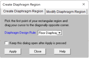
A diaphragm is drawn by clicking the opposite corners of the rectangular area. For regions that have already been created it is possible to update the design rule by clicking the Modify Diaphragm Region tab:

Below are some limitations for drawing diaphragm regions:
Only automatically generated lateral loads (wind, seismic, and notional) are considered for flexible diaphragms. Any user-defined loads are ignored.
If Diaphragm Regions have not been drawn then loads are attributed to all horizontal members within the floor plane (except members perpendicular to load direction). Therefore, drag struts and collectors MUST be modeled in order to get proper load attribution into lateral frames.
If Diaphragm Regions have been drawn then loads are attributed to the perimeter of the diaphragm region, and all members within the region are ignored.
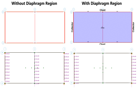
If a diaphragm region has been drawn on a Floor, the total generated lateral load within that region will be attributed to the edges of that diaphragm region, and no other members within that region will receive lateral loads. This allows you to use diaphragm regions to explicitly define load paths in the building.
Note:
For additional advice on this topic, please see the RISA Tips & Tricks website: www.risa.com/post/support. Type in Search keywords: Flexible Diaphragm Design.
Note:
Within the Wood Diaphragm Schedule dialog, you can select between oriented strand board (OSB) or wood structural panels (WSP) databases (plywood or OSB), which have values that are pulled directly from the 2006 IBC. You are also allowed to select between design groups based on cases and whether the diaphragm is blocked or not. You may also specify exact diaphragm parameters by selecting "Use Individual" in the Current Selection Type. For more information on this database, as well as information on how to edit or create your own custom database, see Appendix F-Wood Design Databases
This column allows you to specify the sheathing grade for your diaphragm. The program will then choose a diaphragm selection from the database that has this grade.
These values set minimums and maximums for the thickness of the sheathing that will be designed. If the same value is input for both max and min, then that will be the thickness used.
These values set minimums and maximums for the edge nailing spacing. If the same value is input for both max and min then that nail spacing will be used. These values will only control the outer-most zones of a multi-zone diaphragm region.
The nail spacing increment defines how much the spacing must differ between adjacent zones. The program will design the diaphragm panel with the highest demand for the outer zone, and then step-up the nail spacing by the increment until it finds the next nail spacing that matches all other criteria. This nail spacing will be used to create the next zone.
Diaphragm results can be accessed by the Detail Report button  then clicking on the Flexible Diaphragm perimeter. This opens the Diaphragm Detail Report Key Plan, from which a diaphragm region can be chosen by clicking to review its results.
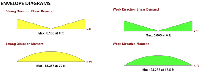
The Diaphragm Region detail report gives detailed information about the diaphragm design. It is split into four main sections: Input, Envelope Diagrams, Design Summary and Chord Force Summary.
For additional advice on this topic, please see the RISA Tips & Tricks webpage at risa.com/post/support. Type in Search keywords: Flexible Diaphragm Design.
Below is the input echo portion of the detail report:

Code – Reports the code used to design the diaphragm.
Design Rule - Lists the Design Rule which has been assigned to this diaphragm region.
Panel Grade – Reports the grade of the panels used in the design (Structural-I, Rated Sheathing, or Other)
Panel Schedule – Reports the nailing schedule database used to optimize panel selection
SGAF - The specific gravity adjustment factor, input in the Diaphragms spreadsheet, reduces the capacity of the diaphragm. Note 2 from Tables A.4.2A-A.4.2C of the NDS 2005 SDPWS gives the calculation of this value as: SGAF = (1 - (0.5 - G)), where G = Specific gravity of the floor framing members.
In addition the basic geometry information for the diaphragm (Total Length, Total Width, Elevation, and L/W Ratio) are also reported here.
The detail report presents envelope diagrams for the shear and moment demand seen on the flexible diaphragm for both the strong and weak directions. The diagrams are color coded yellow for strong direction and green for weak direction for quick reference.
The results for design summary are displayed for both strong and weak directions as shown below.
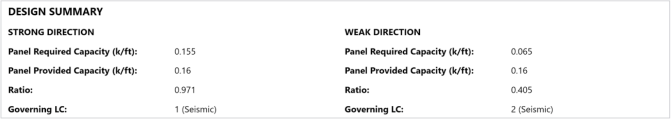
Panel Required Capacity is the scaled maximum design shear, also reported on the envelope diagram. The maximum shear as determined from analysis is compared against Fp for seismic loads. If Fp exceeds the shear as determined by analysis then that shear is scaled up to match Fp. For more information see ASCE7-10, Section 12.10.1.1.
Panel Provided Capacity is the capacity of the designed diaphragm. For diaphragms with multiple nailing zones, this will be reported as capacity at the point of maximum shear. For more information on how the program selects between the various nailing schedules provided in the database, please refer to Appendix F.
The Ratio provides the code check for the diaphragm based on shear demand versus shear capacity.
Governing LC gives the load combination that controls the design. This is based on whichever load combination resulted in the highest ratio for shear capacity. In parentheses it is stated whether the governing load combination was seismic or wind based. If the panel was governed by wind, then you are allowed to use a 40% increase in panel strength. The program will automatically consider this, as long as you have checked the Increase Nailing Capacity for Wind checkbox in the Model Settings-Solution tab.
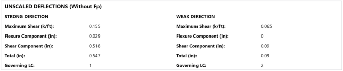
The deflection of a diaphragm is comprised of two main terms, depending on the equation used. The terms are as follows:
The Flexure Component accounts for the deflection of the diaphragm based on bending stresses.
The Shear Component accounts for the deflection of the diaphragm based on shear stresses.
This deflection is based on the actual maximum shears in the diaphragm, which are given. It is not based on the scaled Fp forces, thus we report the unscaled shears.

The chord force summary gives an overall view of the chords on all sides of the diaphragm design region. The chord force calculation is simply the calculated moment divided by the length of the diaphragm (M/L). As the diagram above shows, we will give both tension and compression maximum values, if there are both tension and compression forces for the solved load combinations. The global axes are shown as a reference.
The details of the designed panel are reported here:
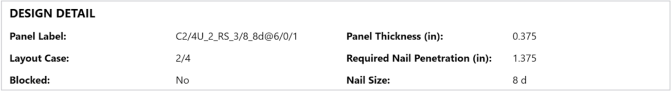
Panel Label - This is the call-out that the program uses to describe the specific panel and nailing. This information is expanded upon afterward.
Layout Case- This reports the case (panel layout) used for the diaphragm design. Because each diaphragm has a strong and weak direction, the program will actually report two cases associated with each diaphragm.

Blocked – This reports whether the diaphragm was designed as blocked or unblocked
Panel Thickness – This reports the decimal thickness of the wood panels. For convenience the following table lists the decimals that correspond with common panel thicknesses:
| Panel Thickness | Decimal Equivalent |
|---|---|
| 5/16 | 0.3125 |
| 3/8 | 0.375 |
| 7/16 | 0.4375 |
| 15/32 | 0.4688 |
| 19/32 | 0.5938 |
Required Nail Penetration – This is the minimum nail penetration as required by the IBC/NDS. This value is taken from the diaphragm nailing schedule/database. For more information on the database refer to Appendix F.
Nail Size - This is the size of the nail required for this call-out.
A diaphragm region is split into various nailing zones. The optimum nailing is chosen from the diaphragm nailing database for the highest point of shear of the diaphragm region in each direction. The program considers the Nail Spacing Increment as defined in the Design Rules. If a nailing arrangement is available that has spacing wider than the sum of the nailing increment and the spacing in the “higher” zone then a new nailing zone can be created. The arrangement of the nailing zones is such that they line up with the threshold shears of the capacities of the zones.

The nail spacing schedule reports the nail spacing for each zone. The zones are shown on a legend below.
Note:
The following information is shown in the nail spacing schedule:
The Zone gives the zone label so you can compare it to the zone layout below.
The Location defines the distance to that zone from the edge of the diaphragm. Note that this is a symmetric distance from either side of the diaphragm.
The Label is giving the call-out for the diaphragm panel.
The Lines entry gives the number of lines of nails on each panel edge. Normally, this value is greater than one only for High-Load diaphragms. This entry is taken directly from the diaphragm nailing schedule database and is not otherwise used in the diaphragm design.
Note:
The Framing Width displays the nominal width required of the framing members that support the diaphragm panels. This entry is taken directly from the diaphragm nailing schedule database and is not otherwise used in the diaphragm design.
The Boundary column gives the required boundary edge nail spacing.
The Cont Edge column gives the required nail spacing at continuous boundary edges that are parallel to the direction of load.
The Other Edge column gives the required nail spacing at all other edges. i.e. edges that are not considered to be boundaries or continuous edges parallel to load.
The collector forces are not currently reported in the Detail Report. However, the applied seismic forces are considered in the normal member design of the collectors. The only issue here is that the seismic forces have not been amplified by the seismic overstrength factor (Ω).
If you think of the diaphragm as a beam with the chord members acting as the flanges, then this is the deflection due to the tension and compression forces that develop in the chords.

v = Maximum shear load in diaphragm region
L = Diaphragm dimension perpendicular to the direction of applied load
E = Chord modulus of elasticity
A = Chord cross-sectional area
W = Diaphragm dimension parallel to the direction of applied load
If you think of the diaphragm as a beam with the diaphragm sheathing acting as the web of the beam, then this component represents the deflection due to the shear forces in the sheathing. This term is based on the apparent shear stiffness (Ga) as described in the NDS Special Design Provisions for Wind and Seismic. As such, this term includes the effects of both elastic shear deformation of the sheathing and nail slip of the panels.
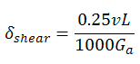
v = Maximum shear load in diaphragm region
L = Diaphragm dimension perpendicular to the direction of applied load
Ga = Apparent diaphragm shear stiffness
For diaphragm regions that have only one zone in each direction the value of Ga is taken directly from the nailing database. For multi-zone diaphragm regions the program internally calculates an equivalent Ga using the formula below:
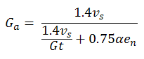
vs = Diaphragm shear capacity (ASD value taken from nailing database)
Gt = Shear stiffness of panel depth (taken from nailing database)
en = Nail slip (taken from nailing diaphragm nailing schedule / database)
α = Nail slip adjustment factor. This factor accounts for non-uniform nail slip across multiple zones, and is derived from the process outlined in the ATC-7 and further explained in the APA design / Construction Guide on Diaphragms and Shears Walls.
The diaphragm key plan is just a plan view of the diaphragms at a given level. The key plan can be accessed by clicking the Detail Report button then click on the Flexible Diaphragm perimeter. This opens the Diaphragm Detail Key Plan, from which a diaphragm region can be chosen by clicking to review its results.
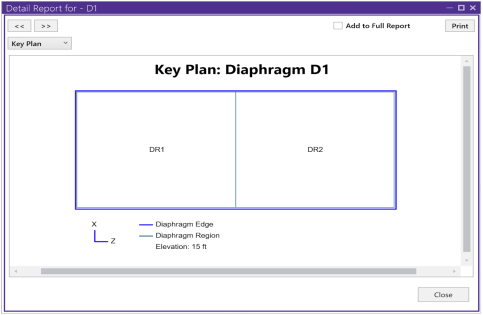
The key plan will list each diaphragm (D1, D2, etc.) and the diaphragm regions within (DR1, DR2. etc.). This key plan is to be used as a summary in RISA-3D for where the diaphragm regions are located within the floor plan. The elevation is also given.
In the future this key plan will give a summary of the diaphragm designs at this level.
Rigid Diaphragms - Currently, the program does not provide any design or code check information for Rigid diaphragms. The rigid diaphragms are solely used to attribute load to the supporting frames or walls.
Unblocked Diaphragm - The program will not optimize multiple nailing zones for unblocked diaphragms.
Chord Slip - The deformation due to chord slip is not considered in the deflections calculations.
Required Framing Size - The detail report lists a required framing nominal width, however no check is performed to ensure that the framing modeled actually meets this requirement.
Diaphragm Loading - The only load seen by flexible diaphragms is the load coming directly from the automatically generated loading. Any loading added in RISAFloor or RISA-3D will not be considered in the design of the diaphragms and will not be attributed to the shear walls.
Sloped Diaphragms - Currently the program will not design sloped flexible diaphragms. At solution in RISAFloor the program will force you to change the diaphragm to rigid. This feature will be added in an upcoming release.
Moisture Content - The program is not considering a reduction in strength due to moisture content.
Orientation - No diaphragm design will be done for regions placed over deck that is not parallel to the Global X and Z axes.
2021 SDPWS Provisions - 2021 SDPWS provisions are not considered for flexible diaphragms.